


Heat Spreader
 A heat spreader is a device having high thermal conductivity that is used to move heat from a concentrated or high heat flux source to a heat exchanger with a larger cross sectional area, surface area and volume. Heat spreaders can be solid conductors like copper, aluminum, or diamond or they can be phase-change devices like heat pipes and vapor chambers.
Functionally, the heat spreader acts as a primary heat exchanger that moves heat between a heat source and a secondary heat exchanger. The secondary heat exchanger is always larger in cross sectional area, surface area and volume. By definition, the heat is “spread out”, such that the secondary heat exchanger has a larger cross sectional area contacting the heat spreader than the heat source. The heat flow is the same in both heat exchangers, but the heat flux density is less in the secondary, so it can be made of a less expensive material such as aluminum, and is a better match to an air heat exchanger, since the low heat transfer coefficient for air convection is adequate for a low heat flux.
Heat Sink
 Heat sinks function by efficiently transferring thermal energy (“heat”) from an object at high temperature to a second object at a lower temperature with a much greater heat capacity. This rapid transfer of thermal energy quickly brings the first object into thermal equilibrium with the second, lowering the temperature of the first object, fulfilling the heat sink’s role as a cooling device. Efficient function of a heat sink relies on rapid transfer of thermal energy from the first object to the heat sink, and the heat sink to the second object.
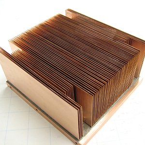
The most common design of a heat sink is a metal device with many fins. The high thermal conductivity of the metal combined with its large surface area result in the rapid transfer of thermal energy to the surrounding, cooler, air. This cools the heat sink and whatever it is in direct thermal contact with. Use of fluids (for example coolants in refrigeration) and thermal interface material (in cooling electronic devices) ensures good transfer of thermal energy to the heat sink. Similarly, a fan may improve the transfer of thermal energy from the heat sink to the air.
Thermal Resistance
This is usually quoted as the thermal resistance from junction to case of the semiconductor device. The units are °C/W. For example, a heatsink rated at 10 °C/W will get 10°C hotter than the surrounding air when it dissipates 1 Watt of heat. Thus, a heatsink with a low °C/W value is more efficient than a heatsink with a high °C/W value. Thermal resistance (R) is the reciprocal of thermal conductivity (k)
Thermal Conductance
Thermal conductanceis the quantity of heat that passes in unit time through a plate of particular area and thickness when its opposite faces differ in temperature by one kelvin. For a plate of thermal conductivity k, area A and thickness L this is kA/L, measured in W·K−1 (equivalent to: W/°C).
Heat Flux
Also (referred to as thermal flux , heat flux density, or heat flow rate intensity) is the heat load per unit of area (W/cm2).
Heat Transfer Coefficient
The heat transfer coefficient is the quantity of heat that passes in unit time through unit area of a plate of particular thickness when its opposite faces differ in temperature by one kelvin (k/L).
Common Thermal Equations
- thermal conductance= kA/L, measured in W·K−1
- thermal resistance= L/(kA), measured in K·W−1 (equivalent to: °C/W)
- heat transfer coefficient= k/L, measured in W·K−1·m−2
When thermal resistances occur in series, they are additive. So when heat flows through two components each with a resistance of 1 °C/W, the total resistance is 2 °C/W.
The following formula can be used to estimate the performance of a simple heat sink.
where:
- Rhsis the maximum thermal resistance of the heat sink to ambient, in °C/W
- ΔT is the temperature difference (temperature drop), in °C
- Pthis the thermal power (heat flow), in watts
- Rsis the thermal resistance of the heat source, in °C/W
For example, if a component produces 100 W of heat, and has a thermal resistance of 0.5 °C/W, what is the maximum thermal resistance of the heat sink? Suppose the maximum temperature is 125 °C, and the ambient temperature is 25 °C; then the ΔT is 100 °C. The heat sink’s thermal resistance to ambient must then be 0.5 °C/W or less.
Heat Pipe
A device that transports heat utilizing the phase change characteristics of a working fluid inside of a tube. Heat pipes have extremely high effective thermal conductivities, typically 10 to 10,000 times more conductive than solid materials.
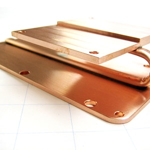
A heat pipe consists of a sealed aluminum or copper container whose inner surfaces have a capillary wicking material. Inside the container is a liquid under its own pressure that enters the pores of the capillary material, wetting all internal surfaces. Applying heat at any point along the surface of the heat pipe causes the liquid at that point to boil and enter a vapor state. When that happens, the liquid picks up the latent heat of vaporization. The gas, which then has a higher pressure, moves inside the sealed container to a colder location where it condenses. Thus, the gas gives up the latent heat of vaporization and moves heat from the input to the output end of the heat pipe. Heat pipes have an effective thermal conductivity many thousands of times that of copper. Heat pipes can be built in almost any size and shape.
Evaporator
The Evaporator is the heat input area (sometimes referred to as the vaporizer). The heat causes the fluid located in the wick structure at this point to boil and enter a vapor state absorbing the thermal energy from the input source based on the fluid’s latent heat of vaporization.
Condenser
The Condenser is the heat output area (sometimes referred to as the radiator). The colder temperature at this location causes the vapor to condense back into a liquid state and become re-entrained into the wick structure. The thermal energy that was absorbed during the vaporization is now released to the output.
For example, if a component produces 100 W of heat, and has a thermal resistance of 0.5 °C/W, what is the maximum thermal resistance of the heat sink? Suppose the maximum temperature is 125 °C, and the ambient temperature is 25 °C; then the ΔT is 100 °C. The heat sink’s thermal resistance to ambient must then be 0.5 °C/W or less.
Heat Pipe Performance
Heat pipes perform much differently than solid conductors that have a fixed thermal resistance. Good heat pipe design requires understanding three controlling resistances in the heat pipe. These three resistances are: Input resistance (Evaporator), Output resistance (condenser), and resistance along the length of the heat pipe. For most designs, the resistance along the length of the heat pipe is so small it is negligible and not even considered. The input, output and joints thermal resistances usually control the performance of the heat pipe.
THERMAL JOINT
The thermal joint is a critical component of the system’s thermal budget. Joining together of multiple components has both mechanical joints and thermal joints. Thermal resistance varies greatly among the different types of mechanical joints. The best are brazed or soldered joints; the worst are “clip on” joints. Minimizing the resistance in the thermal joints is a big factor in the overall system design. There are various strategies that can be employed to combine ease of manufacturing with optimized thermal joint design.
ORIENTATION
The orientation of the heat pipe is important to the overall design and efficiency of the cooling system. While heat pipes function in any direction, it is important to consider the effects of working “with gravity” or “against gravity.”
POWER
The power that is being dissipated as waste heat (typically in W). While power is a necessary design factor of the heat pipe, the watt density (typically in units of power per area) is more of a controlling factor for the overall system design. High heat flux devices usually require more complicated cooling solutions.
TEMPERATURE
The temperature of the component(s) to be cooled, along with the temperature of the cooling medium, are important design factors. The temperature difference between the two, along with the power to be dissipated, provides the targeted thermal resistance for the cooling solution.
HEAT PIPE SHAPES
Heat pipes can be manufactured in a multitude of sizes and shapes. Unusual application geometries can easily be accommodated by Noren Thermal’ ability to shape and form the heat pipes while keeping the wick structure unharmed. If some range of motion is required, flexibility can be built into the heat pipe solution either by design or by material selection. Flat heat pipes are thin in profile and their flat surfaces allow for better thermal contact giving them increased performance. The increased cross sectional area allows for a lower delta T and greater heat transport.
Noren Thermal (NPI) has developed special tube bending tools and procedures which result in optimum performance for factory bent heat pipes regardless of the complexity or number of bends.
WORKING FLUIDS
The more common working fluids for heat pipe designs used for ambient temperature ranges are water and methanol. NPI uses these and more, having developed over 37 different fluid combinations for specific applications.
Heat Pipe Reliability
Heat pipes have been widely accepted in military applications and have high reliability standards. Noren Thermal’ copper-water heat pipes can be expected to operate for over thirty years, far beyond the life/usefulness expected of the electronics.
Have Questions? We're Ready to Help!
Products
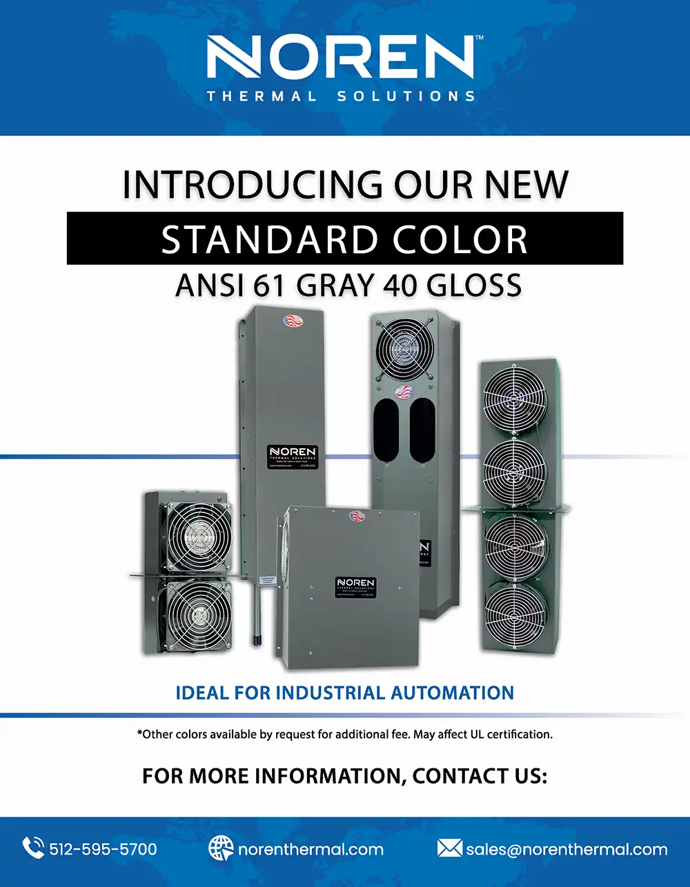
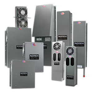
Noren thermal solutions are designed to cool overheating electronics in a variety of industries and applications. Check out our PRODUCTS section for more information.